Calculating Electrical Load Capacity for a Home
The term “electrical load capacity” refers to the total amount of power provided by the main service for use by your home’s branch circuits and the lights, outlets, and appliances connected to them. Understanding capacity and load becomes necessary if you are planning the electrical service for a new home, or if you are considering an electrical service upgrade to an older home. Understanding the load needs will let you choose an electrical service with an appropriate capacity. In older homes, it’s extremely common for the existing service to be badly undersized for the needs of all the modern appliances and features now in use.
Total electrical capacity of an electrical service is measured in amperage (amps). In very old homes with knob-and-tube wiring and screw-in fuses, you may find the original electrical service delivers 30 amps. Slightly newer homes (built before 1960) may have 60-amp service. In many homes built after 1960 (or upgraded older homes), 100 amps is the standard service size. But in large, newer homes, 200-amp service is now as a minimum, and at the very top end, you may see 400-amp electrical service installed.
Understanding Electrical Capacity
Calculating how much power your home needs is a matter of calculating the amperage load of all the various appliances and fixtures, then building in a margin of safety. Generally, it’s recommended that the load never exceeds 80 percent of the electrical service’s capacity.
To use the math, you need to understand the relationship between watts, volts, and amps. These three common electrical terms have a mathematical relationship that can be expressed in a couple of different ways:
Volts x Amps = Watts
Amps = Watts/ volts
Calculating Load
After you know the capacity of individual circuits and of the home’s full electrical service, you can then compare this with the load, which you can calculate simply by adding up the wattage ratings of all the various fixtures and appliances that will be drawing power at the same time.

Breaker Box Safety: How to Connect a New Circuit
We believe in safe DIY. That’s why we’ve always been reluctant to show readers how to open a breaker box and connect a new circuit. Even with the power shut off, there’s a chance you could touch the wrong parts and kill yourself. But then we figured if we didn’t show you, you’d just go search the internet. And that scared us even more. So we’re going to walk you through the process, showing you the safest way to open the breaker box, wire a new breaker and test your work.
Opening the main circuit breaker panel box and adding a circuit is actually pretty easy. You only have to connect three wires to add a circuit, and each circuit wire is color-coded. But there are some safety precautions, and if you ignore them, you could kill yourself. Really. If you follow our safety steps in order and to the letter, you’ll be fine. But if at any point you’re unsure how to proceed or feel uncomfortable with the project, call an electrician.
Get the right parts and tools
Before you go shopping, open the door of your breaker box and copy the manufacturer’s name, the box model number, and the style numbers of the breakers that are approved for your box. Then buy one of those breakers. If your home center doesn’t sell the right model or brand, you’ll have to go to an electrical supplier. You cannot install a circuit breaker style that isn’t specifically approved for use in your box—even if it fits inside the box. While at the store, pick up a few 1/2-in. plastic snap-in cable clamps to secure the new cable. They’re safer than metal clamps because you don’t put your hand in the panel to install them
Power down, then remove the cover
Turn off all computers in the house before you switch off the power. Then switch off the main breaker (the service disconnect) and follow the panel box cover removal procedure shown in the photo
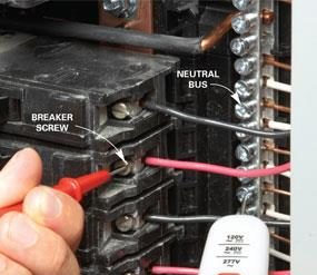
Test to make sure it’s dead
It’s dangerous to assume the power is really off just because you’ve flipped the service disconnect to the off position. There’s a slim chance that the service disconnect didn’t work properly, keeping power to some breakers. So test each and every breaker to make sure it’s really dead. If the test light lights up, stop and call an electrician.
Preventing Electrical Overloads
Understanding Electrical Overloads
Every December, the neighbor across the street lights up the block with an elaborate holiday light display. Four-foot plastic angels stand in ranks, 3-ft. candles dot the landscape, elves pop out from behind plastic snow figures, and Santa in his loaded sleigh skims across the roof with a cluster of reindeer
But every year dozens of outdoor light displays like this unexpectedly go out. You might have plugged in a small electric heater and turned it on to warm your feet. Or switched on a hair dryer. Or dropped a snack into the toaster. It’s not only the outdoor display that goes out, but perhaps most of the main floor lights too. The TV in the family room quits. The clock in the kitchen stops. And later an electrician tells you that the refrigerator stopped running too.
The problem? An overloaded circuit. The power needed by the outdoor lights added to the load from the refrigerator, the heater and any other devices connected to the same circuit, and all of them running at once exceeded the capacity of the electrical wiring
Figure A: Circuit With an Overload
An electrical circuit with too many electrical devices turned on can exceed the circuit limit. Circuit breakers or fuses will automatically shut off the circuit at the main panel.
Circuit logic
The nerve center of your electrical system is the main panel, usually a gray metal box about the size of a cookie sheet, that typically sits in some obscure spot in a utility room, the garage or the basement. Three large wires from the utility company feed the main panel. Although you might spot the wires outside if they’re overhead, they’ll be encased in conduit inside for safety, because they contain virtually unlimited electrical power.

Electric circuit
Electric circuit, path for transmitting electric current. An electric circuit includes a device that gives energy to the charged particles constituting the current, such as a battery or a generator; devices that use current, such as lamps, electric motors, or computers; and the connecting wires or transmission lines. Two of the basic laws that mathematically describe the performance of electric circuits are Ohm’s law and Kirchhoff’s rules.
Electric circuits are classified in several ways. A direct-current circuit carries current that flows only in one direction. An alternating-current circuit carries current that pulsates back and forth many times each second, as in most household circuits. (For a more-detailed discussion of direct- and alternating-current circuits,
The network of transistors, transformers, capacitors, connecting wires, and other electronic components within a single device such as a radio is also an electric circuit. Such complex circuits may be made up of one or more branches in combinations of series and series-parallel arrangements.

Electric circuits
Student everyday experiences
Students have plenty of experience using everyday household appliances that rely on electric circuits for their operation ( torches, mobile phones, iPods). They very likely have developed a sense that you need a battery or power switch to be turned on to make things ‘work’, and that batteries can go ‘flat’. They tend to think of electric circuits as involving something they call ‘current’ or ‘energy’ or ‘electricity’ or ‘voltage’, all labels which they often use interchangeably. This is unsurprising given that all these labels are frequently used in everyday language with unclear meaning. Whichever label students use, they are likely to see electric circuits as involving ‘flow’ and something being ‘stored’, ‘used up’, or both. Some everyday language, for example about ‘charging batteries,’ may also be a source of conceptual confusion for students.
Specifically, students often see current as being the same as voltage, and think current can be stored in a battery, and that current may be used up or transformed into a form of energy, like light or heat.
‘the unipolar model’ – the view that only one wire is actually needed between the battery and the light bulb for there to be a current in the circuit.
‘the clashing currents model’ – the view that current ‘flows’ from both terminals of the battery and ‘clashes’ in the light bulb.
‘the current consumed model’ – the view that current is ‘used up’ as it ‘goes around’ the circuit so the current ‘flowing towards’ the light bulb is greater than the current ‘flowing away’ from it back to the battery.